Home/blog/10 Projects You Can Build With A Multimeter/
10 Projects You Can Build With A Multimeter
August 5th , 2026 | AstroAI *
Student Electronics • Low-Voltage Projects • 2026
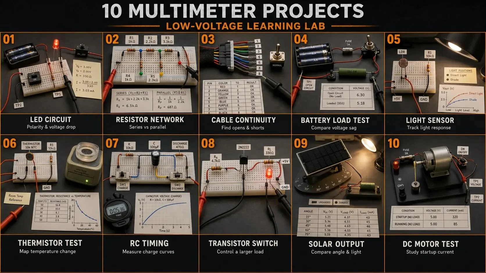
Ten structured laboratory scenarios, from component verification and sensor response to solar-output and low-voltage motor-load studies.
10 Projects You Can Build With A Multimeter
A multimeter does more than confirm whether a circuit works. It shows why the circuit behaves as it does. With a low-voltage battery or current-limited bench supply, a breadboard, a few components, and a suitable meter, you can build projects that teach voltage division, resistance, continuity, diode polarity, current draw, sensor response, capacitor timing, transistor switching, solar output, and motor behavior.
The ten projects below are arranged from beginner to intermediate. Each includes the meter function, a repeatable test method, the result to expect, and a practical troubleshooting path. They are educational low-energy projects, not instructions for testing household outlets, electrical panels, high-voltage systems, or high-energy battery packs.
Quick Answer: Which Project Should You Start With?
Brand new to electronics: begin with LED polarity, a resistor network, or a cable continuity tester.
Learning analog circuits: build the light-sensor voltage divider, thermistor response circuit, and capacitor timer.
Learning controls or mechatronics: try the transistor switch, solar characterization, and low-voltage DC motor project.
Choosing a meter: AM33B covers the foundational projects, DM130B is the balanced choice for most of the list, and DM6000AR adds True RMS, frequency, duty-cycle, capacitance, and temperature capability for deeper experiments.
Universal rule: predict the result first, measure second, repeat the reading, and record the circuit state, range, units, and test points.
Before You Build
Use only instructor-approved low-voltage batteries or current-limited supplies and components rated for the circuit. De-energize and discharge the circuit before measuring resistance, continuity, diode behavior, or capacitance. Confirm the black lead is in COM, the red lead is in the correct input, and the meter function matches the measurement before power is applied.
Current measurement is different from voltage measurement: a standard multimeter must become part of the circuit in series, and its input limit must not be exceeded. Return the red lead to the normal voltage/resistance input immediately after a current test.
AstroAI Project Recommendations
Choose the Meter by the Projects You Want to Build
These are different starting points, not a price-based ranking. A simpler meter can be better for learning fundamentals; a broader meter is useful only when its additional functions match the project.
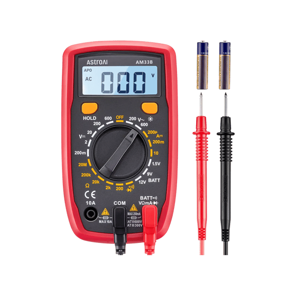
Best for: students who want one meter for nearly all ten projects, including direct capacitance checks and mixed AC/DC current work.
Verified summary: AC/DC voltage and current up to 10A, resistance, continuity, diode, capacitance, automatic ranging, NCV screening, backlight, Data Hold, and automatic power-off.
Pros: Automatic ranging speeds repeated tests and capacitance extends the project range.
Cons: Current still requires a series connection, and the model is not True RMS.
Not best for: Projects that specifically require True RMS, frequency, duty-cycle, or temperature measurement.
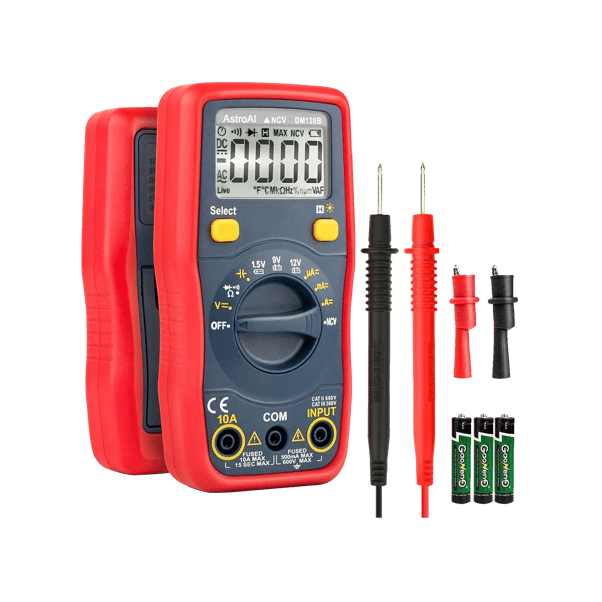
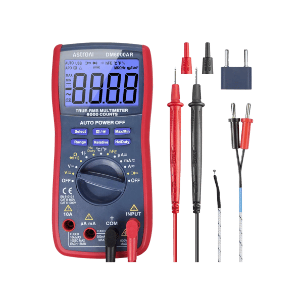
Best for: students extending the projects into capacitor characterization, frequency, duty-cycle, temperature, and waveform-dependent AC measurements.
Verified summary: automatic and manual ranging, AC/DC voltage and current up to 10A, True RMS, resistance, continuity, diode, capacitance, frequency, duty-cycle, and temperature measurement.
Pros: The broadest measurement set in this group and more display counts for finer shown increments.
Cons: More functions take longer to learn, and it remains a handheld meter rather than an oscilloscope or data logger.
Not best for: The simplest first project when only voltage, resistance, continuity, and diode checks are required.
This table compares published capabilities. It does not claim independent accuracy, durability, or calibration performance. Select from the functions the project actually uses and confirm the printed ratings and manual before testing.
Model
Counts
Range / RMS
Voltage / Current
Project Functions
Best Match in This Guide
AM33B
2000
Manual; not True RMS
AC/DC voltage to 600V; DC current to 10A
Resistance to 20 MΩ, continuity, diode, hFE, Data Hold
Projects 1–6, 8, and basic 9–10
DM130B
4000
Automatic; not True RMS
AC/DC voltage to 600V; AC/DC current to 10A
Resistance to 40 MΩ, continuity, diode, capacitance, NCV, Data Hold
Balanced choice across all 10 projects
DM6000AR
6000
Automatic and manual; True RMS
AC voltage to 750V; DC voltage to 1000V; AC/DC current to 10A
Resistance to 60 MΩ, continuity, diode, capacitance, frequency to 60 MHz, duty cycle, temperature
Projects 6–10 and advanced extensions
The 10-Project Learning Path
No.
Project
Main Meter Functions
What You Learn
1
LED polarity and resistor board
Diode, DC voltage, resistance
Polarity, forward voltage, current limiting, and voltage drop
2
Series and parallel resistor map
Resistance, DC voltage
Equivalent resistance, tolerance, and node voltage
3
Cable and switch continuity tester
Continuity, resistance
Open circuits, contact resistance, and wire mapping
4
Battery comparison under a small load
DC voltage
Open-circuit voltage, loaded voltage, and internal resistance effects
5
Light-sensor voltage divider
Resistance, DC voltage
Sensor response, voltage division, and orientation
6
Thermistor response indicator
Resistance, DC voltage, optional temperature
Temperature-dependent resistance and sensor calibration
7
Capacitor charge and discharge timer
DC voltage, optional capacitance
RC time constant and exponential change
8
Transistor-controlled LED switch
Diode, DC voltage, DC current, optional hFE
Control current, load current, and saturation behavior
9
Small solar panel angle study
DC voltage, controlled DC current
Light intensity, angle, load, and output variation
10
Low-voltage DC motor load study
DC voltage, DC current, resistance
Starting current, running current, voltage sag, and load effects
10 Multimeter Projects, Step by Step
Use component values and supply limits approved by your instructor, kit documentation, or component datasheets. The formulas below help predict behavior, but the rated limits of every component and instrument still control the build.
Project 1 • Beginner
Build an LED Polarity and Current-Limiting Resistor Board
You need: low-voltage source, breadboard, LED, suitable resistor, jumper wires, and a multimeter with diode, resistance, and DC voltage modes.
Build: place the LED and resistor in series. Estimate the resistor with R = (Vs - Vf) / I, then choose a standard value that keeps current below the LED rating.
Test: de-energize the board to identify LED polarity in diode mode and verify resistor value. Power the board, then measure supply voltage, LED voltage, and resistor voltage without moving the red lead to a current jack.
Expected result: the LED lights only with correct polarity. The measured drops should approximately add to the supply voltage. LED forward voltage varies with LED type, current, and temperature.
Project 2 • Beginner
Map a Series and Parallel Resistor Network
You need: three or more resistors, breadboard, low-voltage source, and resistance/DC voltage modes.
Build: create one series network and one parallel network. Predict series resistance by addition and parallel resistance from 1/Rtotal = 1/R1 + 1/R2 + ....
Test: measure each resistor out of circuit, then measure each completed network with power removed. Apply low voltage and record node voltages.
Expected result: series resistance is larger than any individual resistor; parallel resistance is lower than the smallest branch resistor. Real readings differ slightly because of component tolerance and contact resistance.
Project 3 • Beginner
Make a Cable and Switch Continuity Tester
You need: spare low-voltage cable, switch, connector or terminal strip, labels, and continuity/resistance modes.
Build: wire several conductors through a connector and place a switch in one path. Label only one end so the far-end mapping must be discovered.
Test: disconnect every power source. Short the probes together to learn the lead resistance and beep response, then map each conductor and compare the switch-open and switch-closed states.
Expected result: a closed path shows low resistance and usually activates the continuity alert; an open path shows overload or a very high reading. The beep threshold is model-dependent, so use the resistance value when the distinction matters.
Project 4 • Beginner
Compare Batteries at Rest and Under a Small Load
You need: same-type low-voltage batteries, holder, switch, properly rated resistor load, and DC voltage mode.
Build: connect the approved load through a switch so the battery can be measured open-circuit and under the same repeatable load.
Test: record open-circuit voltage, close the switch briefly for the loaded reading, then allow the battery to rest. Use the same load time for every sample and stop if the resistor or battery warms.
Expected result: two batteries can show similar open-circuit voltage but different loaded voltage. A larger drop can indicate higher internal resistance or lower available charge, but this simple project is not a full battery-capacity test.
Project 5 • Intermediate
Build a Light-Sensor Voltage Divider
You need: photoresistor, fixed resistor, breadboard, low-voltage source, and resistance/DC voltage modes.
Build: connect the photoresistor and fixed resistor as a divider. The output at their junction follows Vout = Vs × Rbottom / (Rtop + Rbottom).
Test: with power removed, measure the photoresistor in bright and shaded conditions. Power the divider, then record output voltage at several repeatable light levels. Reverse the component positions and repeat.
Expected result: photoresistor resistance changes with illumination, and reversing its divider position reverses whether output voltage rises or falls with light.
Project 6 • Intermediate
Build a Thermistor Response Indicator
You need: thermistor, fixed resistor, breadboard, low-voltage source, and resistance/DC voltage modes; a temperature-capable meter can provide a separate reference.
Build: make a voltage divider with the thermistor and fixed resistor. Check whether the thermistor is NTC or PTC before predicting the direction of change.
Test: measure resistance at room temperature with power removed. Warm the thermistor gently with your fingers or another approved mild source, never an open flame, then record resistance and divider voltage after the reading stabilizes.
Expected result: an NTC thermistor decreases in resistance as temperature rises; a PTC device increases. The output-voltage direction also depends on where the thermistor sits in the divider.
Project 7 • Intermediate
Observe a Capacitor Charge and Discharge Curve
You need: low-voltage source, resistor, suitable capacitor, switch, stopwatch, and DC voltage mode; capacitance mode is optional for checking the component first.
Build: connect the resistor and capacitor as an RC circuit. Predict the time constant with τ = R × C. Observe capacitor polarity when using a polarized type.
Test: fully discharge through an approved resistor, never by directly shorting the terminals. Start the timer as charging begins and record voltage at regular intervals; then repeat while discharging through the resistor.
Expected result: after one time constant, capacitor voltage reaches about 63% of the final charging change or falls to about 37% during discharge. Hand timing, tolerance, and meter loading create small differences.
Project 8 • Intermediate
Build a Transistor-Controlled LED Switch
You need: low-voltage source, suitable transistor, LED, current-limiting resistor, base or gate resistor, switch, and diode/DC voltage modes; hFE is optional for compatible bipolar transistors.
Build: use the transistor as a low-side switch. Select resistor values from the transistor and LED limits rather than relying on hFE alone.
Test: de-energize to identify junction behavior in diode mode. Power the circuit and compare control voltage, load voltage, and transistor voltage in the off and on states. Measure current only if the expected value is safely inside the selected input.
Expected result: a small control signal switches a larger LED current. In the on state, LED current flows and the transistor's controlled-path voltage becomes relatively low when the circuit is designed for switching.
Project 9 • Intermediate
Characterize a Small Solar Panel by Light and Angle
You need: small educational solar panel, stable light source or sunlight, angle guide, approved resistor load, and DC voltage mode; controlled current mode is optional.
Build: mount the panel so its angle can be repeated, then connect a resistor load that stays within the panel and meter limits.
Test: record open-circuit voltage, then voltage across the same load at several angles and light levels. If measuring current, place the meter in series with the load. Do not short the panel through the current input unless the panel documentation and instructor procedure explicitly permit that test.
Expected result: loaded output changes with illumination, angle, shading, and temperature. Open-circuit voltage alone does not describe the power available to a load.
Project 10 • Intermediate
Study Low-Voltage DC Motor Current and Voltage Sag
You need: small educational DC motor, approved low-voltage supply, switch, optional mechanical load, and DC voltage/current modes.
Build: create a fused or current-limited motor circuit with accessible test points. Confirm expected motor current is comfortably below the meter input and supply limits.
Test: measure motor winding resistance only while disconnected and de-energized. Record supply voltage before start, during startup, and while running. For current, place the meter in series using the correct input. Apply only a normal instructor-approved load; do not intentionally stall the motor.
Expected result: startup current is usually higher than steady running current, and supply voltage may sag more during startup or increased load. Stop immediately if the motor, wiring, supply, or meter warms unexpectedly.
Repeatable Project Evaluation
How to Test Any Multimeter Project Fairly
Use the same workflow for every build. It separates prediction, construction, measurement, and diagnosis so a correct-looking number is not accepted without context.
1
Define the expected result. Calculate or estimate the voltage, resistance, current, polarity, or time response before connecting the meter.
2
Inspect the circuit and instrument. Check component ratings, polarity, wiring, power source, lead condition, input jacks, fuses, function, range, and printed limits.
3
Verify passive parts with power removed. Measure resistance, continuity, diode behavior, or capacitance only after de-energizing and discharging the circuit.
4
Power the circuit and measure voltage first. Confirm supply polarity and voltage at the source, then move through defined test points without changing to the current jack.
5
Measure current only when necessary. De-energize, move the red lead to the correct fused current input, insert the meter in series, start on a safe range, and stop before approaching the input limit.
6
Repeat under one controlled change. Change only light, temperature, load, switch state, angle, resistance, or time interval so the cause of the reading change remains clear.
7
Record and explain the difference. Save three readings with units, range, test points, circuit state, and environmental conditions, then compare them with the prediction and component tolerances.
How the Projects Fit Different Learning Goals
Introductory circuits
Projects 1–4 teach polarity, voltage drop, equivalent resistance, continuity, and the difference between open-circuit and loaded voltage.
Analog electronics and sensors
Projects 5–7 turn changing resistance and capacitance into measurable voltage and time responses. They are useful preparation for data acquisition and control systems.
Embedded systems and robotics
Projects 5, 6, 8, and 10 connect sensor inputs and transistor outputs to the electrical behavior a microcontroller must eventually read or control.
Energy and sustainability
Projects 4 and 9 show why source voltage alone does not describe useful energy delivery. Adding a controlled load exposes voltage sag and available output.
Mechanical and mechatronics
Projects 6 and 10 connect temperature, motor load, starting current, and supply behavior to physical systems.
Technical troubleshooting
Project 3 develops a disciplined de-energized diagnostic process that transfers to connectors, switches, wiring harnesses, and low-voltage control circuits.
Common Project Mistakes
Measuring resistance on a powered circuit: remove power and discharge first.
Leaving the red lead in the current jack: return it immediately after current testing.
Changing several variables at once: change one condition so the result can be explained.
Ignoring component tolerance: a small difference from calculation is not automatically a fault.
Using continuity beep as a precise resistance test: read the resistance value when it matters.
Shorting a battery, capacitor, solar panel, or supply: use approved loads and procedures.
Ignoring probe resistance and contact quality: short the leads first and inspect the test points.
Recording numbers without units: always record range, unit, polarity, test points, and circuit state.
How We Selected the Projects, Meters, and Specifications
The projects were selected to create a progression through common meter functions without requiring household mains or high-energy systems. The product comparison uses current published lineup data and model details checked on August 4, 2026. Selection was based on project coverage and measurement method rather than price, rating, or popularity.
Choose Projects 1–3 if this is your first time using a multimeter. AM33B supports the essential learning steps and makes range selection visible. DM130B is the most balanced choice for completing the full list with automatic ranging and capacitance. DM6000AR is the stronger extension when you want to study frequency, duty cycle, temperature, True RMS AC, and more detailed capacitor behavior. Whichever meter you use, the learning comes from predicting, measuring, repeating, and explaining the difference.
What is the easiest multimeter project for a beginner?
An LED polarity and resistor board is a strong first project because it combines resistance, diode mode, polarity, and DC voltage without requiring current measurement. A cable continuity tester is another simple starting point.
Can I complete these projects with a basic multimeter?
A basic meter with DC voltage, resistance, continuity, diode, and DC current can complete most core activities. Capacitance, frequency, duty-cycle, and temperature functions allow additional checks and extensions but are not required for every build.
Do I need a breadboard for every project?
No. A breadboard is useful for LED, resistor, sensor, capacitor, and transistor circuits. Cable, battery, solar, and motor projects can use suitable holders, connectors, switches, and secured low-voltage wiring.
Why should voltage be measured before current?
Voltage measurement is usually less disruptive and confirms supply polarity and level without opening the circuit. Current measurement requires a correct series connection and the proper fused input, so it should be added only after expected current is understood.
Can a multimeter show an entire capacitor charge curve?
A handheld multimeter can provide individual voltage readings at timed intervals, which can be plotted afterward. It is not a replacement for an oscilloscope or data logger when continuous waveform capture or fast timing is required.
Is a continuity beep the same as zero resistance?
No. Continuity mode activates below a model-specific threshold, and the leads and contacts also add resistance. Use the displayed resistance value when contact quality or conductor resistance matters.
Can I test a household outlet as one of these projects?
No. These projects are designed for instructor-approved low-voltage circuits. Household outlets, electrical panels, mains-powered appliances, and high-energy systems require appropriate training, equipment, ratings, and procedures.
Which AstroAI meter covers the most project extensions?
DM6000AR covers the broadest extension set among the three models compared here because it adds True RMS, frequency, duty-cycle, temperature, and capacitance measurement. DM130B remains the more streamlined choice when those functions are not required.