1. Measurement
A digital multimeter checks voltage, resistance, continuity, diode behavior, and supported current. It answers the first troubleshooting question: what is actually happening at this point in the circuit?
August 13th , 2026 | AstroAI *
Student Electronics Guide
A useful first electronics lab kit does not need every instrument on day one. Start with five capabilities: measure a circuit, build it without solder, power it at low voltage, handle small parts, and organize the results. That means a digital multimeter, breadboard and jumper wires, a current-limited low-voltage source, a focused component assortment, basic hand tools, and labeled storage.
Buy first: a multimeter, full-size breadboard, solid-core jumper kit, regulated low-voltage supply with current limiting, resistor and LED assortment, switches, capacitors, diodes, transistors, wire cutter, small pliers, and parts storage.
Add later: soldering equipment, oscilloscope, function generator, logic analyzer, specialty sensors, and higher-power supplies only when a project or course requires them.
Learn safely: begin with battery-powered or isolated low-voltage circuits. Do not use a first student kit for outlets, breaker panels, appliance mains, high-energy batteries, or other hazardous systems.
This staged approach keeps the kit affordable, but the larger benefit is educational: every purchase has an immediate task. The meter verifies assumptions, the breadboard makes changes reversible, current limiting reduces damage when wiring is wrong, and a lab notebook turns isolated experiments into repeatable engineering work.
Build in Stages
The right order is measurement first, prototyping second, controlled power third, and specialization last. Buying an oscilloscope before learning to verify voltage, resistance, and continuity often creates more buttons without creating better observations.
| Stage | What to Add | Capability Gained | Wait Until... |
|---|---|---|---|
| Day One | Multimeter, breadboard, jumpers, low-voltage power, core components, cutter, pliers, notebook | Build and troubleshoot DC circuits without solder | Nothing; these tools support the first exercises |
| After 3-5 Projects | Alligator leads, mini hooks, potentiometers, buzzer, more semiconductors, spare breadboard | Faster measurement and more interactive circuits | You know which connection problems slow you down |
| When Circuits Become Permanent | Temperature-controlled iron, stand, tip cleaner, solder, fume extraction, safety glasses, desoldering tool | Assemble and repair durable low-voltage boards | A breadboard design works and supervision is available |
| When Signals Matter | Oscilloscope, logic analyzer, function generator, better probes | Observe waveforms, timing, digital buses, and changing signals | A project asks a question a multimeter cannot answer |
A digital multimeter checks voltage, resistance, continuity, diode behavior, and supported current. It answers the first troubleshooting question: what is actually happening at this point in the circuit?
Use a full-size solderless breadboard, pre-cut solid-core jumpers, flexible male-to-female leads, and a printed or hand-drawn map of the breadboard's connected rows and power rails.
Choose a regulated, isolated low-voltage source with adjustable current limiting when possible. Current limiting is more educational than repeatedly replacing components after a wiring mistake.
Start with common resistor values, LEDs, pushbuttons, potentiometers, small capacitors, rectifier and signal diodes, general-purpose transistors, and a low-voltage buzzer.
Flush cutters, wire strippers, fine-tip pliers, tweezers, and a small screwdriver set cover most mechanical work. Add eye protection before cutting leads.
Keep a notebook, labels, divided storage, and a simple inventory. Record the schematic, supply setting, expected values, measured values, and each change you make.
Large assortments look impressive but can hide basic gaps. A smaller, labeled set makes it easier to understand what each part changes.
| Category | Useful Starting Selection | What Students Learn |
|---|---|---|
| Resistors | 220 Ω, 330 Ω, 1 kΩ, 4.7 kΩ, 10 kΩ, 100 kΩ | Ohm's law, voltage dividers, LED current limiting, pull-up and pull-down behavior |
| Indicators and Controls | Red, green, and blue LEDs; momentary buttons; 10 kΩ potentiometer | Polarity, current limits, switching, analog input, and variable resistance |
| Capacitors | 100 nF ceramic; 1 µF, 10 µF, and 100 µF electrolytic | Decoupling, polarity, charging delay, and why capacitance requires a suitable meter or calculation |
| Semiconductors | Signal diode, rectifier diode, general-purpose NPN transistor | Forward voltage, one-way conduction, base control, and transistor pin identification |
| Connections | Breadboard, jumper wires, battery holder, alligator clips, spare test leads | Node identification, ground reference, contact resistance, and systematic continuity checks |
The Measurement Anchor
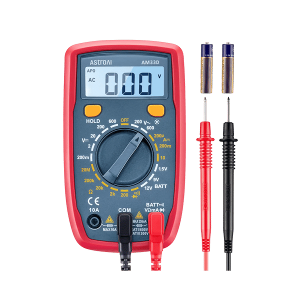
Best for: low-voltage breadboard circuits, batteries, resistance checks, continuity tracing, diode exercises, and learning how measurement ranges work.
Pros: the manual dial encourages students to identify the quantity and expected range before touching the circuit; the core functions cover many introductory DC exercises.
Cons: no AC current, True-RMS, capacitance, frequency, temperature, or NCV measurement. A later course may require a more capable meter.
Not best for: waveform analysis, precision capacitance or frequency labs, non-sinusoidal AC measurements, or advanced coursework that explicitly requires auto-ranging and additional functions.
Safety boundary: a printed category and voltage rating is an equipment limit, not permission for an inexperienced user to probe mains circuits. This guide keeps first projects at isolated low voltage.
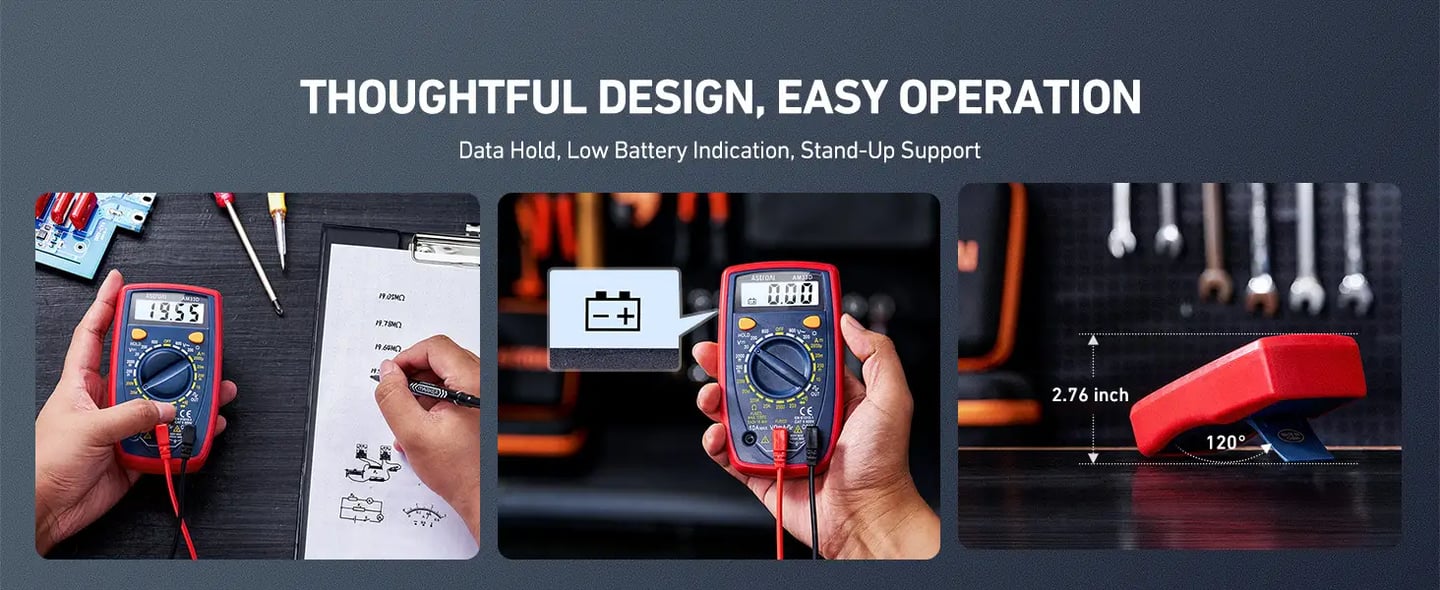
View AstroAI AM33DBefore measuring, students must predict whether a value is likely to be millivolts or volts, ohms or kilohms. Start above the expected value and move down for better resolution. If the display shows an overload indication, select a higher range. This prediction-measurement-comparison loop is more valuable than simply obtaining a number.
A consistent bench layout prevents many beginner mistakes. Even a small desk can be divided into functional zones.
Breadboard in the center, schematic beside it, power disconnected while wiring changes are made.
Meter stable and readable, leads routed away from loose parts, correct input jacks verified before every reading.
Only parts for the current project are open. Every drawer or bag is labeled with value and component type.
Supply off or disconnected by default, voltage and current limit recorded before connection.
Each step adds one capability and one verification habit. Complete them in order rather than buying everything at once.
Learn by Measuring
PROJECT 1
With all power removed, identify connected rows, separated center channels, and split power rails. Draw the internal map and verify it with the continuity function.
PROJECT 2
Read color bands, predict each resistance, measure it with power disconnected, calculate percentage difference, and sort any mislabeled parts.
PROJECT 3
Use a low-voltage source and series resistor. Predict the voltage across the resistor and LED, then measure each voltage without moving the current lead into the wrong jack.
PROJECT 4
Compare forward and reverse readings for LEDs and ordinary diodes. Record how color, device type, and probe direction affect the result.
PROJECT 5
Choose two resistors, calculate the expected midpoint voltage, build the circuit, measure the result, and explain any difference using resistor tolerance and meter loading.
| Mistake | Why It Causes Trouble | Better Habit |
|---|---|---|
| Buying by item count | Huge assortments may repeat uncommon parts and omit useful values | Buy against the next five schematics |
| Skipping current limiting | A wiring error can overheat parts before the student locates it | Set voltage and a conservative current limit before connection |
| Measuring before predicting | Unexpected readings become numbers without context | Write an expected range and polarity first |
| Leaving the lead in the current jack | The next voltage measurement can create a near-short | Return the lead immediately after current measurement |
| Adding advanced tools too early | Bench space and attention go to equipment with no defined question | Upgrade when the current kit reaches a named limitation |
Begin with a meter, breadboard, controlled low-voltage power, a deliberate component set, hand tools, and documentation. The AstroAI AM33D supports the foundational measurements used in many first exercises while requiring students to think about function and range.
Use the first five projects to expose real gaps. If the kit cannot observe a changing waveform, add a suitable waveform tool. If a proven circuit needs to become permanent, add supervised soldering equipment. Every upgrade should answer a question that the current bench cannot.
Start with a digital multimeter, full-size breadboard, jumper wires, regulated current-limited low-voltage power, common resistors and semiconductors, switches, LEDs, basic cutters and pliers, eye protection, labeled storage, and a lab notebook.
Yes, for introductory low-voltage work that needs AC/DC voltage, DC current, resistance, continuity, diode, or hFE testing. It is manual range, so students learn to estimate values. It does not measure AC current, capacitance, frequency, temperature, or True-RMS.
Usually not. First learn voltage, resistance, continuity, diode checks, breadboarding, and controlled power. Add an oscilloscope when a project requires waveform shape, timing, ripple, noise, or another changing signal a multimeter cannot show.
No. A solderless breadboard is better for first circuits because connections are reversible. Add temperature-controlled soldering equipment, ventilation, eye protection, and supervision when a tested design needs to become permanent.
Use a regulated, isolated low-voltage source with adjustable current limiting when possible. Set the voltage and current limit before connecting the circuit. Avoid improvised mains supplies, damaged battery packs, and unknown chargers.
Choose common resistors, several LED colors, pushbuttons, a potentiometer, ceramic and electrolytic capacitors, signal and rectifier diodes, a general-purpose transistor, and a low-voltage buzzer. Buy parts that appear in the next few projects rather than maximizing assortment size.
Manual ranging makes the student predict the magnitude before measuring. Starting above the expected value and moving down for resolution reinforces units, scale, overload indications, and the connection between calculations and observations.
This guide does not recommend it. Students should begin with isolated, current-limited low-voltage circuits. Mains work requires appropriate training, procedures, supervision, environment-specific equipment, and correctly rated probes and instruments.