Multimeter Troubleshooting Guide | August 17, 2026
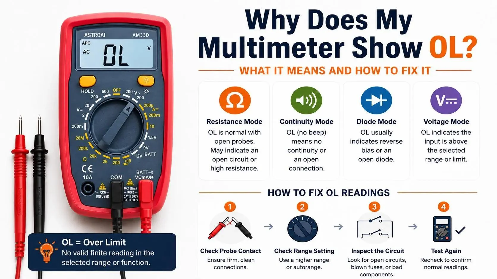
Why Does My Multimeter Show OL? What It Means and How to Fix It
OL means the meter cannot display a valid finite reading in the selected function and range. In resistance or continuity mode, OL is normal when the probes are separated because there is no conductive path. Across a wire, fuse, switch, or resistor, the same display may point to an open circuit, poor probe contact, a resistance above the meter's range, or a manual range that is set too low. In voltage mode, OL more often means the selected range or measurable input limit has been exceeded.
Quick Answer: Normal OL vs. OL That Needs Investigation
Normal OL: The probes are not touching in resistance or continuity mode; a good diode is reverse-biased; or an autoranging meter is briefly searching for the correct range.
Likely setup issue: The red lead is in the wrong jack, the meter is on the wrong function, a manual resistance or voltage range is too low, the probe tips are touching paint or corrosion, or a lead is damaged.
Likely circuit fault: The probes and setup pass a known-good check, but an isolated wire, fuse, switch, resistor, or connection still shows OL where a closed low-resistance path should exist.
Some manuals call OL an overload or over-limit indication, while users may describe it as "open loop" or "open line." The most useful interpretation is not the expansion of the letters. It is the combination of the selected mode, range, probe position, and circuit condition.
Before Troubleshooting an OL Reading
Resistance, continuity, and diode tests are normally performed on a de-energized circuit. Disconnect power, discharge capacitors according to the equipment instructions, and verify that stored energy is removed before testing.
Do not move the dial to resistance or continuity while the probes are connected to a live circuit. For mains, panels, high-energy batteries, or unfamiliar systems, use correctly rated equipment and leave the work to a trained user.
Also inspect the meter case and leads before use. Do not use cracked insulation, exposed conductor, loose plugs, a damaged input jack, or a meter whose rating does not match the measurement environment.
What OL Means in Each Multimeter Mode
Use this table before deciding that the meter, test lead, or circuit has failed.
| Mode |
When OL Is Normal |
When OL May Indicate a Problem |
First Check |
| Resistance |
Probes apart, an intentionally open switch, or resistance above the available range. |
Open resistor, broken wire, blown fuse, poor contact, wrong jack, or manual range set too low. |
De-energize, touch probes together, then select a higher range if manual. |
| Continuity |
Probes apart or a path whose resistance is above the meter's continuity threshold. |
A path expected to be closed remains OL and silent after the leads and contacts pass checks. |
Confirm the continuity symbol is active and short the probe tips together. |
| Diode |
Reverse-bias testing of many healthy diodes. |
OL in both directions may indicate an open diode, poor contact, or an in-circuit measurement affected by the board. |
Reverse the probes and compare both directions with the component isolated when practical. |
| Voltage |
A brief autoranging transition can occur while the meter searches for a usable range. |
Selected manual range is too low, the input exceeds the meter's range, or the wrong voltage function is selected. |
Stop, confirm AC or DC, input jacks, meter rating, and a higher appropriate range. |
Why Resistance Mode Keeps Showing OL
A resistance measurement works by applying a small test signal and looking for a conductive path. With the probes suspended in air, there is no complete path, so OL is the expected display. The same is true for an open switch.
When testing a component, OL means the measured resistance is too high for the selected range or no path is being detected. On a manual-ranging meter, move to a higher resistance range before calling the component open. If the highest available range still shows OL, verify probe contact and isolate the component from parallel circuit paths when practical.
- Wrong manual range: A resistor can exceed the selected range even though it is not open.
- Insulated contact point: Paint, oxidation, conformal coating, oil, or dirt can prevent the probe tip from reaching metal.
- Open component: A failed resistor, thermal fuse, filament, winding, or wire can produce OL.
- Unstable in-circuit result: Capacitors and parallel paths can make the display change or delay. Discharge safely and isolate one side of the component when the procedure requires it.
Why Continuity Mode Shows OL and Does Not Beep
Continuity mode is a fast low-resistance test, not a universal test for whether any current path exists. The buzzer operates only below a model-specific resistance threshold. A long wire, lamp, motor winding, coil, semiconductor path, or corroded connection may conduct yet remain above that beep threshold.
First short the probe tips together. A working meter in continuity mode should normally leave OL, show a reading near zero, and sound its buzzer. If it does not, confirm the function selection, the red lead's V/Ω input, the black lead's COM input, lead condition, and battery state.
Probes Apart
OL and no beep are normal. The test path is intentionally open.
Probes Touching
A near-zero reading and beep are expected. Persistent OL points to setup, contact, lead, battery, or meter trouble.
Across the Test Item
OL can indicate a true open only after the meter, probes, contacts, and test setup have been verified.
OL in Diode and Voltage Modes
Diode Mode
Many healthy diodes conduct in one direction and block in the other. A forward-biased diode should show a forward-voltage reading that depends on diode type and test conditions; reversing the probes often produces OL. OL in both directions can point to an open diode or poor contact, but in-circuit parallel paths can change the result.
Voltage Mode
In voltage mode, do not interpret OL as an open wire. It usually means the selected range cannot represent the input or the input is beyond the instrument's measurable range. On a manual-ranging meter, start with the highest appropriate AC or DC voltage range when the voltage is unknown, then step down for better resolution. On an autoranging meter, wait for the range to settle, but stop if OL persists.
Do not keep probing an unknown source just to see whether OL clears. Confirm the expected voltage, AC/DC type, input jacks, selected function, and the meter and lead ratings before continuing.
How to Troubleshoot a Multimeter That Keeps Showing OL
Work through these checks in order. They separate a normal display state from a setup problem, damaged lead, out-of-range reading, and true open circuit.
-
1
Make the test safe.
For resistance, continuity, and diode checks, disconnect power and discharge stored energy according to the equipment instructions before connecting the probes.
-
2
Verify the selected function.
Confirm resistance, continuity, diode, AC voltage, or DC voltage is actually active. On shared dial positions, use the Select or Function button until the intended symbol appears.
-
3
Check the input jacks.
Insert the black lead fully into COM and the red lead into the voltage/resistance input. Do not leave the red lead in a current input for these checks.
-
4
Short the probe tips together.
In resistance or continuity mode, touching the metal probe tips together should replace OL with a low reading and normally trigger the continuity buzzer. Persistent OL means the test system needs attention before the circuit is judged.
-
5
Inspect and flex the leads.
Look for split insulation, loose plugs, damaged tips, or intermittent readings while the leads are gently moved. Replace damaged leads with correctly rated compatible leads.
-
6
Correct the range.
On a manual-ranging meter, move to a higher appropriate range. On an autoranging meter, hold steady contact and allow the display to settle; if manual range mode was engaged, return to auto or select a higher range.
-
7
Improve probe contact and isolate the item.
Touch clean bare metal with firm, stable pressure. When the procedure allows, disconnect one side of a component so parallel circuit paths do not disguise its condition.
-
8
Compare with a known-good path.
Test a known-good short path or component in the same mode. If the meter and leads respond normally there but the original isolated path remains OL, a true open or out-of-range high resistance is more likely.
Four Real Scenarios and the Correct Conclusion
| Scenario |
What OL Means |
Correct Next Step |
| Resistance mode, probes floating |
Normal open test path. |
Touch the probes together to confirm the meter leaves OL, then test the de-energized component. |
| Manual meter on 2 kΩ, testing 10 kΩ |
Selected range is too low. |
Select the next higher resistance range that can include the expected value. |
| Continuity test across a removable fuse |
Possible blown fuse, but not proven yet. |
Remove power, verify the probes beep together, clean the fuse contacts, and test the isolated fuse again. |
| Voltage mode shows OL on an unknown source |
Range or input limit may be exceeded. |
Stop and confirm AC/DC type, expected voltage, jacks, selected range, and equipment ratings before continuing. |
Autoranging vs. Manual Ranging: Why the Same Circuit Can Show OL
Manual-Ranging Meter
You select a measurement range. OL can appear simply because the expected value is higher than that selected range.
Best response: Start high when the value is unknown, then step down until the reading has useful resolution without exceeding the range.
Autoranging Meter
The meter chooses the range. OL may flash briefly while it searches, but persistent OL means no finite reading was found within the available ranges or the path is open.
Best response: Hold the probes steady, allow the display to settle, and verify that the meter has not been switched into manual range mode.
Autoranging reduces range-selection mistakes, but it cannot repair poor probe contact or identify circuit context for you. Manual ranging makes the range limit visible and can be useful for learning why OL appears. Both types require the same safety checks and correct lead placement.
Two Practical Starting Points
Choose a Meter That Matches How You Want to Learn
OL troubleshooting is easier when the meter's range behavior matches your experience. These two models support resistance and continuity testing but teach range selection differently.
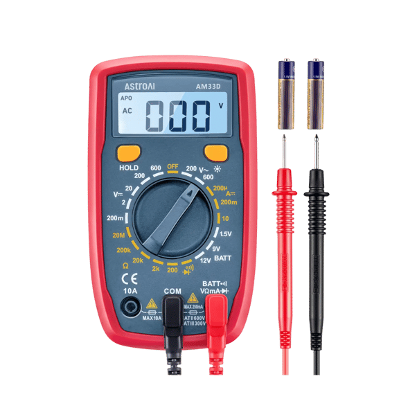
Manual range learning
AstroAI AM33D 2000-Count Digital Multimeter
Verified summary: A 2000-count manual-ranging meter with AC/DC voltage, DC current, resistance, continuity, diode, and battery testing.
Best for: Beginners learning how selected ranges affect resistance and voltage readings.
Pros: If OL disappears after moving to a higher resistance range, the meter demonstrates the difference between an over-range reading and a true open circuit.
Cons / Not best for: Manual range selection adds one more decision to every measurement, and AM33D is not the right choice for users who need AC current measurement.
View AM33D
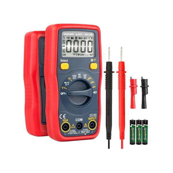
Easier automatic range selection
AstroAI DM130B 4000-Count Autoranging Digital Multimeter
Verified summary: A 4000-count autoranging meter with AC/DC voltage and current, resistance, continuity, capacitance, diode, NCV screening, and dedicated battery test positions.
Best for: Users who want the meter to select the range during routine electronics, battery, and household troubleshooting.
Pros: Autoranging removes the most common manual range mismatch, making persistent OL easier to trace to contact, setup, or the test item.
Cons / Not best for: Autoranging may take a moment to settle, and DM130B is not best for users who need the added frequency and temperature functions of a more advanced meter. NCV is only a screening function, not a substitute for a properly performed contact measurement.
View DM130B
A higher display count does not automatically solve an OL reading. Correct mode, range, probe contact, and circuit isolation remain the decisive checks.
Common Mistakes That Turn a Simple OL Into a Wrong Diagnosis
- Calling a fuse blown before proving the probes and continuity mode work.
- Testing resistance on an energized circuit or before capacitors are safely discharged.
- Leaving the red lead in the current jack while trying to measure resistance or voltage.
- Holding probes on paint, oxidation, plastic, or conformal coating instead of clean metal.
- Treating no continuity beep as proof that no electrical path exists at any resistance.
- Ignoring the selected manual range or not allowing an autoranging meter to settle.
- Testing a component in circuit and assuming surrounding parallel paths cannot affect the result.
The Practical Rule for Any OL Reading
Ask four questions in order: Which mode am I in? Is the selected range appropriate? Do the probes and jacks pass a self-check? Should this exact test point provide a conductive path?
OL is normal when the test path is open by design. It becomes evidence of a circuit fault only after the meter setup, leads, contact points, range, and component isolation have been checked.
Frequently Asked Questions
What does OL mean on a multimeter?
OL means the meter cannot display a valid finite reading in the selected function and range. Depending on the mode, it can indicate an open test path, a value above the selected range, or an input beyond the meter's measurable range.
Why does my multimeter show OL when measuring resistance?
In resistance mode, OL means no resistance value was found within the selected range. The causes include separated probes, a manual range that is too low, poor contact, resistance above the meter's limit, or a genuinely open component or conductor.
Is OL normal when the probes are not touching?
Yes. In resistance or continuity mode, separated probes create an open test path, so OL and no continuity beep are normal.
Why is there no beep in continuity mode?
The path may be open or its resistance may be above the meter's continuity threshold. If the probes also fail to beep when touched together, check the selected function, input jacks, lead condition, probe contact, and battery before judging the circuit.
Does OL always mean a wire or fuse is broken?
No. OL can be caused by the normal open state, a range that is too low, poor probe contact, wrong lead placement, or a damaged test lead. A true open is more likely only after the setup passes a known-good check.
Why does OL disappear when I select a higher range?
The measured value was higher than the previous manual range could display. Moving to a higher range brought the value within the meter's displayable range; it does not mean the component changed.
What does OL mean in diode mode?
OL commonly appears when a diode is reverse-biased and blocking the meter's test current. OL in both directions can indicate an open diode or poor contact, while in-circuit paths may affect either result.
What should I do if voltage mode shows OL?
Stop and confirm the expected voltage, AC or DC function, input jacks, selected range, and meter and lead ratings. On a manual meter, use a higher appropriate range; do not continue if the source may exceed the instrument's rating.
Official Product References